Category
- Products
-
- Wiki
- Contact us

Inverter manufacturers
![]() sales@inverters.cn
sales@inverters.cn
Home » Application
Reconstruction scheme
Condenser pump is one of main auxiliary equipments in turbine system. It brings condensing water to deaerator through heating. Because of constant speed operation, flow only can be controlled by valve. Great throttle loss, high outlet pressure, damage on pipe and low efficiency lead to frequent leakages and energy waste. Furthermore, this kind of mechanic adjustment structure has bad quality, linearity and low switch rate. Frequent adjustments cause lots of faults, which increases maintenance cost and wastes resources.
2 100% capacity condenser pumps are equipped with 300MW generator. Model is 9LDTNA4. Rated flow is 841m3/h. Water lift is 280m. Speed is 1480rpm. Asynchronous motor power is 1000KW. During reconstruction, we add MV inverter to implement stepless adjustment. Power varies with load variety. It heightens efficiency and optimizes operation. Reconstruction complies tenet of "small change, more reliability, best economic benefit".
Advantages: make full use of existing equipment; low cost; keep original control mode same and ensure motor to run in direct on line when inverter is broken; easy maintenance.
Disadvantages: complicated connection; need to add MV breaker; need to add close circuit.
Normal operation: take an example of 51# pump in variable frequency state. Power goes to inverter through 50# switch, then output to 51# motor through 510#. At this time, direct on line switch of 52# is spare. Logics of each switch is following:
Conditions of switch on in direct on line:

Conditions of switch on of inverter
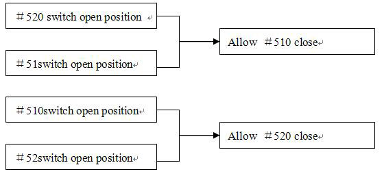
Operation process is following when a pump is broken.
When the pump controlled by inverter is broken, the other pump switches to direct on line automatically (same as original switch mode). When the broken pump is well repaired, it switches to variable frequency state. The spare pump runs only in direct on line, cannot run in variable frequency state.
Condenser pump is one of main auxiliary equipments in turbine system. It brings condensing water to deaerator through heating. Because of constant speed operation, flow only can be controlled by valve. Great throttle loss, high outlet pressure, damage on pipe and low efficiency lead to frequent leakages and energy waste. Furthermore, this kind of mechanic adjustment structure has bad quality, linearity and low switch rate. Frequent adjustments cause lots of faults, which increases maintenance cost and wastes resources.
2 100% capacity condenser pumps are equipped with 300MW generator. Model is 9LDTNA4. Rated flow is 841m3/h. Water lift is 280m. Speed is 1480rpm. Asynchronous motor power is 1000KW. During reconstruction, we add MV inverter to implement stepless adjustment. Power varies with load variety. It heightens efficiency and optimizes operation. Reconstruction complies tenet of "small change, more reliability, best economic benefit".
Advantages: make full use of existing equipment; low cost; keep original control mode same and ensure motor to run in direct on line when inverter is broken; easy maintenance.
Disadvantages: complicated connection; need to add MV breaker; need to add close circuit.
Normal operation: take an example of 51# pump in variable frequency state. Power goes to inverter through 50# switch, then output to 51# motor through 510#. At this time, direct on line switch of 52# is spare. Logics of each switch is following:
Conditions of switch on in direct on line:

Conditions of switch on of inverter

Operation process is following when a pump is broken.
When the pump controlled by inverter is broken, the other pump switches to direct on line automatically (same as original switch mode). When the broken pump is well repaired, it switches to variable frequency state. The spare pump runs only in direct on line, cannot run in variable frequency state.
4# boiler (75t) of coal gangue plant of circulating flow bed boiler. Technics of boiler is following: burning is low temperature burning. Fuel is delivered to boiler chamber by coal feed system. Primary air entrances to fire box from air distributor bottom, ensuring material fluidization. The secondary air entrances along height class, increasing oxygen to ensure full burning. Materials of fire box vibrate intensively by fluidization air action. Part of solid materials are brought to boiler chamber by high speed air flow. Some big granules flow along chamber inside by gravitation. Some small granules entrance material separator following flue gas. Gas and solid are forming inside chamber. After separation of solid and gas, granules left return to fire box. Gas separated leaves boiler. Because boiler has separator of high efficiency, granules left return to chamber. Ash concentration of chamber is high. Circulating flow bed boiler differs from common boiler which only has radiation heat transfer. Circulating flow bed boiler also has other heat transfer modes such as convection, which heightens heat transfer coefficient of chamber greatly, ensures boiler to reach rated output. Circulating flow bed boiler has low requirement for coal quality. Its pollution material discharging is very low. So it is boiler of environmental protection which is promoted widely by state.
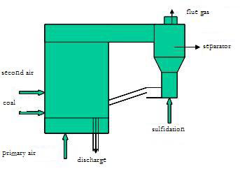

Introduction of reconstruction
1) Parameters
a. mill fan: 2
b. parameters of mill fan
Motor parameters
c. Work parameters: air flow of single fan 48000 m3/h, yearly work time 5850h. Average current is 40A when motor runs in direct on line.
d. Power price: 0.24 Yuan /kWh
2) Equipment after reconstruction
The system is composed of inverter and bypass cabinet. In above figure, QS1, QS2 and QS3 are all in bypass cabinet. QF and M are original equipment.
The system has switch function between line frequency and variable frequency. QS2 and QS3 cannot close together. They are mechanical interlock. During variable frequency operation, QS1 and QS2 close, QS3 opens. During line frequency operation, QS3 closes, QS1 and QS2 open.
3. Mill fan Technics
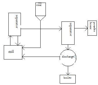
Mill fan is installed behind of ball mill, raw powder separator and fine powder separator. In ball mill, raw coal mixes with hot air and recycle air from outlet of mill fan. Raw coal is dried and grindered into coal powder. With negative air flow produced by mill fan, fine powder separator separates air from powder. Coal powder drops in warehouse as storage. Residual gas contains 5~10% mixture of air and powder. It is delivered to furnace as tertiary air, or mixes with coal powder left as primary air. Mixture is delivered to furnace. From above processes, we see mill fan provides negative pressure for system. After reconstruction with frequency inverter, outlet gate of mill fan is full open. Meanwhile, adjust outlet gate appropriately. It can meet requirement of providing negative pressure completely, without affection on tertiary air.
1) Parameters
a. mill fan: 2
b. parameters of mill fan
| Model | M6-31No20D | Rated flow (qv, max) | 78000 m3/h |
| Rated pressure (Pa) | 13235 | speed (NO) | 1450 r/min |
Motor parameters
| Model | Y5601-4 | Rated voltage (UO) | 6000V |
| Rated power (Pdn) | 630kW | Efficiency (η) | 96% |
| Rated current (IO) | 71A | Power factor (cosФ) | 0.87 |
| speed (NO) | 1485r/min | | |
c. Work parameters: air flow of single fan 48000 m3/h, yearly work time 5850h. Average current is 40A when motor runs in direct on line.
d. Power price: 0.24 Yuan /kWh
2) Equipment after reconstruction
The system is composed of inverter and bypass cabinet. In above figure, QS1, QS2 and QS3 are all in bypass cabinet. QF and M are original equipment.
The system has switch function between line frequency and variable frequency. QS2 and QS3 cannot close together. They are mechanical interlock. During variable frequency operation, QS1 and QS2 close, QS3 opens. During line frequency operation, QS3 closes, QS1 and QS2 open.
3. Mill fan Technics

Mill fan is installed behind of ball mill, raw powder separator and fine powder separator. In ball mill, raw coal mixes with hot air and recycle air from outlet of mill fan. Raw coal is dried and grindered into coal powder. With negative air flow produced by mill fan, fine powder separator separates air from powder. Coal powder drops in warehouse as storage. Residual gas contains 5~10% mixture of air and powder. It is delivered to furnace as tertiary air, or mixes with coal powder left as primary air. Mixture is delivered to furnace. From above processes, we see mill fan provides negative pressure for system. After reconstruction with frequency inverter, outlet gate of mill fan is full open. Meanwhile, adjust outlet gate appropriately. It can meet requirement of providing negative pressure completely, without affection on tertiary air.
Scheme selection
In order to save cost, we considered to use hydraulic coupling ever. But we finally gave up this method as its much maintenance, long installation period. After research, considering advanced technology and mature product, we decide to use medium voltage inverter. In several inverter brands such as ABB, Gozuk, Siemens, we decide to use Gozuk inverter because of its advanced technology and the cost-effective.
Model selection
1) Motor is 6kV/450kW. The frequency inverter current is a key parameter. The inverter capacity is designed according to motor rated current and max current. So inverter should meet following conditions:
η: efficiency 0.85
cosφ: power factor 0.75
Um: voltage
Im: current
K: revised coefficient of current waveform (1.05~1.1).
Pcn:inverter capacity (KVA). Icn:inverter rated current(A).
2) connecting method: one drive one bypass circuit

3) Control principle: PLC implements pressure PI control, ensures pipe pressure constant, outputs 4~20mA signal to inverter to implement auto control of speed. Equip upper PC on inverter. Install upper PC in control room, start/stop, adjust inverter through upper PC. Frequency inverter data and state shows in upper PC.
4) Link lock protection of isolator, inlet valve, outlet valve and pump fault.
5) Set over current protection, low speed protection.
6) Protection action: by PLC.
In order to save cost, we considered to use hydraulic coupling ever. But we finally gave up this method as its much maintenance, long installation period. After research, considering advanced technology and mature product, we decide to use medium voltage inverter. In several inverter brands such as ABB, Gozuk, Siemens, we decide to use Gozuk inverter because of its advanced technology and the cost-effective.
Model selection
1) Motor is 6kV/450kW. The frequency inverter current is a key parameter. The inverter capacity is designed according to motor rated current and max current. So inverter should meet following conditions:
Pcn≥(KPm)/(ηcosφ) (KVA)Pm: output power
Icn≥KIm (A)
Pcn≥K√3UmIm*10-3 (KVA)
η: efficiency 0.85
cosφ: power factor 0.75
Um: voltage
Im: current
K: revised coefficient of current waveform (1.05~1.1).
Pcn:inverter capacity (KVA). Icn:inverter rated current(A).
2) connecting method: one drive one bypass circuit

3) Control principle: PLC implements pressure PI control, ensures pipe pressure constant, outputs 4~20mA signal to inverter to implement auto control of speed. Equip upper PC on inverter. Install upper PC in control room, start/stop, adjust inverter through upper PC. Frequency inverter data and state shows in upper PC.
4) Link lock protection of isolator, inlet valve, outlet valve and pump fault.
5) Set over current protection, low speed protection.
6) Protection action: by PLC.
Scheme selection
By looking through relevant material and inquiry from other power plants, our plant put forward to adopt variable frequency adjustment. Existing practice proves that this method has considerable effect of energy saving. We also made comparison and analysis between variable frequency adjustment and hydraulic coupling adjustment. We went to Haikou Power Plant and asked for information, finding following disadvantages of hydraulic coupling: complicated system, low reliability, much maintenance labour. Its advantages is low price and low cost. Through analysing actual state, the plant did not have enough installation space for hydraulic coupling. So we gave up hydraulic coupling and decided to use variable frequency adjustment.
Introduction of variable frequency adjustment
With consecutive development, variable frequency technology has reached a high level and has applied in several industries and civil facilities, such as civil variable frequency air conditioner. Its character is to utilize open/close loop control. Power cells of inverter output power required through AC-DC-AC single phase inverter circuit. Frequency inverter makes output frequency meet technics requirement, thereby reaching goal control and purpose of energy saving.
The plant selected and purchased Gozuk inverter at last. The inverter is high-high voltage source inverter, adopting cell-cascaded and multi level technology, with advantages of less harmonic, better output waveform.
Reform implementation
Because 6kV switch room has no enough installation space, plant decided to install one inverter for each surplus heat boiler. Frequency inverter has function of "one drive two". It can drive P1, P2, and has bypass function. Two boilers use two inverters. The two inverters drive four pumps.
Reconstruction began in August, 2004. The whole installation and commissioning finished within a week.
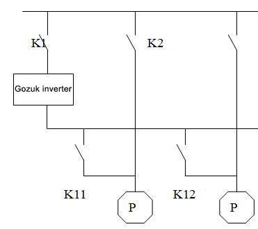
Introduction of operation mode
For above reasons, we must adopt special operation mode to ensure safe operation of water feeding system. We selected following mode eventually.
During normal operation, variable frequency pump works. System adopts HP steam drum close loop control. Water feeding governing valve is in manual control and full open. Standby pump in direct on line does not join link start, which can prevent trip-off resulted from high water level of HP steam drum when personnel does not take measure in time.
In the case of failure of inverter or running pump, it stops automatically or by manual. Personnel should start standby pump manually and adjust appropriate opening of valve as per load of that time. Exit HP steam drum three low value protection, avoid tripping caused by lag control. The gist is that surplus heat boiler has capacity of dry burning. Anyway, these ask for high requirement to personnel. When the frequency inverter is broken, original running pump can use line power to become as standby pump, thereby making high serviceability of water feeding system, reducing probabilities of stop farthest.
By looking through relevant material and inquiry from other power plants, our plant put forward to adopt variable frequency adjustment. Existing practice proves that this method has considerable effect of energy saving. We also made comparison and analysis between variable frequency adjustment and hydraulic coupling adjustment. We went to Haikou Power Plant and asked for information, finding following disadvantages of hydraulic coupling: complicated system, low reliability, much maintenance labour. Its advantages is low price and low cost. Through analysing actual state, the plant did not have enough installation space for hydraulic coupling. So we gave up hydraulic coupling and decided to use variable frequency adjustment.
Introduction of variable frequency adjustment
With consecutive development, variable frequency technology has reached a high level and has applied in several industries and civil facilities, such as civil variable frequency air conditioner. Its character is to utilize open/close loop control. Power cells of inverter output power required through AC-DC-AC single phase inverter circuit. Frequency inverter makes output frequency meet technics requirement, thereby reaching goal control and purpose of energy saving.
The plant selected and purchased Gozuk inverter at last. The inverter is high-high voltage source inverter, adopting cell-cascaded and multi level technology, with advantages of less harmonic, better output waveform.
Reform implementation
Because 6kV switch room has no enough installation space, plant decided to install one inverter for each surplus heat boiler. Frequency inverter has function of "one drive two". It can drive P1, P2, and has bypass function. Two boilers use two inverters. The two inverters drive four pumps.
Reconstruction began in August, 2004. The whole installation and commissioning finished within a week.

Introduction of operation mode
For above reasons, we must adopt special operation mode to ensure safe operation of water feeding system. We selected following mode eventually.
During normal operation, variable frequency pump works. System adopts HP steam drum close loop control. Water feeding governing valve is in manual control and full open. Standby pump in direct on line does not join link start, which can prevent trip-off resulted from high water level of HP steam drum when personnel does not take measure in time.
In the case of failure of inverter or running pump, it stops automatically or by manual. Personnel should start standby pump manually and adjust appropriate opening of valve as per load of that time. Exit HP steam drum three low value protection, avoid tripping caused by lag control. The gist is that surplus heat boiler has capacity of dry burning. Anyway, these ask for high requirement to personnel. When the frequency inverter is broken, original running pump can use line power to become as standby pump, thereby making high serviceability of water feeding system, reducing probabilities of stop farthest.
Variable frequency speed adjustment: it adopts advanced
power and electronic technology, computer control technology and
communication technology. So it has advantages over other adjustment
modes.
So the plant selects the most advanced adjustment mode---variable frequency adjustment. By evaluating numerous inverter manufacturers, the plant decided to use Gozuk inverter. The frequency inverter has following advantages:
- The inverter has LCD interface and touch screen panel which can show voltage, current, frequency, speed at any time. Personnel can observe motor state at any time.
- High frequency resolution and adjustment precision meet technics requirement completely.
- The inverter has universal external ports which can connect to PLC and control machine, and also can connect to original control circuit, composing close loop system, such as data exchange and linkage with original DCS.
- The inverter has local control and remote control through internet.
- The inverter has power protection and electric protection which ensure inverter and motor reliable during normal operation and failure.
- Motor can realize soft start/stop. Start current is smaller than rated current of motor. Start time can be adjusted continuously, reducing affection on power grid.
- The inverter reduces wear and tear on auxiliary components, prolongs equipment lifetime and heightens production efficiency.
So the plant selects the most advanced adjustment mode---variable frequency adjustment. By evaluating numerous inverter manufacturers, the plant decided to use Gozuk inverter. The frequency inverter has following advantages:
- Gozuk takes the biggest market share in China. System runs reliably.
- It has perfect HMI.
- It has distinct technology predominance at reliability and safety.
- Inside PLC changes control logic easily, applicable to site need.
Tags: inverter, Power Plant
Most fans and water pumps are selected
according to its full loads working status, but in practice they are not
working at the full load state in most of the time. So to control flow
& air volume of the pumps & fans, it needs a wind deflector,
reflux valve or start/stop timer usually, and the large power ac motors
are very difficult in start/stop frequently as the electric impact is in
a high level, during this time, it's absolutely will cause electric
energy wasted and high current impact during start/stop of the ac motor.
To solve this kind of problem, the most scientific way is to adopt a Gozuk inverter (AC Drive) to control the fans and water pumps. When the AC motor operates at 80% of its rated rotation speed, in theory, the power consumption is the cube of 80% of its rated power, i.e. 51.2%. Generally, it can almost save 40% power consumption for the manufacturer when deduct the impact of mechanical loss and ac motor copper and iron loss. Plus, it can improve energy-efficient when the fan & pump adopt closed-loop constant-pressure control which can be achieved easily. Due to the inverter can realize soft start/stop for the ac motors, it can avoid voltage surge during the motor's start period to decrease the failure rate and increase its service life, and reduce the power system's capacity requirements and reactive power loss.
Energy Conservation Analysis
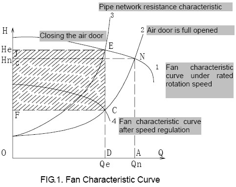
Through the fluid mechanics' basic principles, we know the fans and pumps are belong to square torque loads, the rotation speed n, flow Q, pressure H and shaft power P relation: Q?n, H?n2, P?n3, i.e., the flow is in proportion to its rotation speed, the pressure is in proportion to the square of its rotation speed, and the shaft power is in proportion to the cube of its rotation speed.
We now take the fan as an instance of the principle in energy conservation. As show in following fig, when the fan in its rated rotation speed, the air volume and air pressure change as curve 1, which intersects with the pipe network resistance curve 2 at the rated working condition point N when the air door is full opened; the air volume of the fan is Qn and the pressure is Hn. Normally, the working condition point is moved to point E by closing the regulation air door and increasing the resistance in ventilation pipe network. At this moment, the air volume is decreased to Qe and the generated pressure head is He. If the air volume is regulated by reducing the rotation speed of the fan, the fan will operate as curve 4, and re-generate required air volume Qe, it will intersect with the pipe network resistance curve 2 at the working condition point C when the air door is full opened.

With the development of economy, energy saving and emission reduction
are key points in future. Technology of medium voltage variable
frequency is promoted increasingly. This paper demonstrates inverter
design, electrical connecting, thermal control logic configuration,
commissioning and benefits in condenser pump.
Equipment parameters
Condensing water system is middle pressure system, equipped with condenser pump. Parameters are following:
Operation state before reform
Condensing pump runs in constant speed. After being boosted pressure by pump, condensing water passes through axes and governing valve (inlet gate of deaerator, serial No C-1), then enters into deaerator. Condensing flow is controlled by governing valve opening to maintain stability of water level of deaerator. In addition, condensing water is also supplied to other auxiliary equipments. In order to avoid condensing system superpressure and cavitation during operation in low load, we design recycle pipeline. (see following figure).
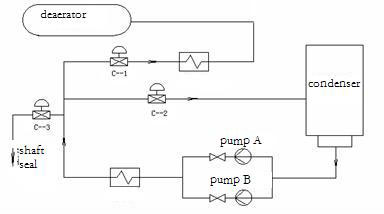
Circulating governing valve C-2 cooperates with C-1 to adjust water level of deareator, keeps normal pressure for system.
Equipment parameters
Condensing water system is middle pressure system, equipped with condenser pump. Parameters are following:
| Motor parameters | |||||
| Model | YLKK500--4 | Rated voltage (U0) | 6kV | Cooling mode G | Q161 |
| Rated power (Pdn) | 1120kW | Speed (n0) | 1491r/min | Insulation class | F |
| Rated current (I0) | 124.7A | Power factor | 0.901 | IP class | IP54 |
| Condenser pump parameters | |||||
| Rated flow | 912.98m3/h | Rated speed | 1480r/min | Rated lift | 258.4m |
| Power | 1120kW | Model | NLT350 - 400*6 | ||
Operation state before reform
Condensing pump runs in constant speed. After being boosted pressure by pump, condensing water passes through axes and governing valve (inlet gate of deaerator, serial No C-1), then enters into deaerator. Condensing flow is controlled by governing valve opening to maintain stability of water level of deaerator. In addition, condensing water is also supplied to other auxiliary equipments. In order to avoid condensing system superpressure and cavitation during operation in low load, we design recycle pipeline. (see following figure).

Circulating governing valve C-2 cooperates with C-1 to adjust water level of deareator, keeps normal pressure for system.
This application introduces frequency inverter in ID fan reconstruction.
Inverter not only saves energy, but also improves start-up of motor and
fan, prolongs lifetime of equipment.
Inverter Structure
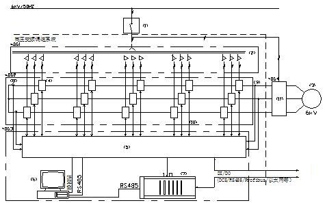
In general, the load of the unit varies in the range of 50%~100%. Generator output power varies. Forced air flow and induced air flow of boiler vary correspondingly. ID fan is adjusted by changing angle of blade. Although there is energy-saving to some extent contrast to damper adjustment. The loss is still considerable, especially in the situation of low load. Secondly the slow adjustment of static blade may lead to the load lag correspondingly. Generally, the starting current of asynchronous motor is 8~10 times of the rated current, which may surge the power grid. Big torque also affects lifetime of motor and fan badly.
When the speed of the fan varies, the efficiency varies a little. The flow is directly proportional to speed. Pressure is directly proportional to the square of the speed, and shaft power is directly proportional to the cube of the speed. Furthermore, the shaft power would reduce in cube relation when the speed is down, so does the motor power. Then we know that speed adjusting is the key of energy-saving for fans. It could achieve linear adjustment for ID fan with inverter.
Frequency inverter can optimize the operation of the motor and enhance efficiency greatly to save energy. There were some restrictions before, such as price, reliability, capacity etc. inverter was not widely used. Recently, with the rapid development of power devices, control theory and computer science, declining price of inverter and increasing reliability, MV inverter has been widely used in auxiliary equipment of power plants.
Inverter Structure

In general, the load of the unit varies in the range of 50%~100%. Generator output power varies. Forced air flow and induced air flow of boiler vary correspondingly. ID fan is adjusted by changing angle of blade. Although there is energy-saving to some extent contrast to damper adjustment. The loss is still considerable, especially in the situation of low load. Secondly the slow adjustment of static blade may lead to the load lag correspondingly. Generally, the starting current of asynchronous motor is 8~10 times of the rated current, which may surge the power grid. Big torque also affects lifetime of motor and fan badly.
When the speed of the fan varies, the efficiency varies a little. The flow is directly proportional to speed. Pressure is directly proportional to the square of the speed, and shaft power is directly proportional to the cube of the speed. Furthermore, the shaft power would reduce in cube relation when the speed is down, so does the motor power. Then we know that speed adjusting is the key of energy-saving for fans. It could achieve linear adjustment for ID fan with inverter.
Frequency inverter can optimize the operation of the motor and enhance efficiency greatly to save energy. There were some restrictions before, such as price, reliability, capacity etc. inverter was not widely used. Recently, with the rapid development of power devices, control theory and computer science, declining price of inverter and increasing reliability, MV inverter has been widely used in auxiliary equipment of power plants.
This article introduces inverter principle and its commissioning at
site, analyses energy saving effect and gives reference to understand
inverter operation.
Electrical system is 'one drives one' mode (dashed line parts is the added).
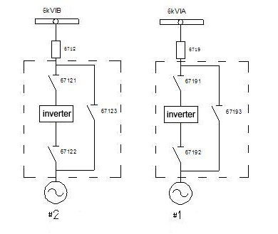
Medium voltage inverter can switch operation mode according to need. For example: mode of one runs in variable frequency and the other runs in direct on line, and mode of the both run in direct on line. The disadvantage is that during switching, load needs to be adjusted. After lowering load, stop 1# (or 2#) ID fan, then switch the operation mode. In normal state, two ID fans run in variable frequency.
Medium voltage inverter has local control and remote control. In remote control, speed signal from DCS trails inverter speed and makes feedback. In local control, remote control is invalid.
There is auto and manual modes when inverter is controlled by DCS. In manual state, personnel controls inverter speed by changing in interface to realize negative pressure adjustment.
Electrical system is 'one drives one' mode (dashed line parts is the added).

Medium voltage inverter can switch operation mode according to need. For example: mode of one runs in variable frequency and the other runs in direct on line, and mode of the both run in direct on line. The disadvantage is that during switching, load needs to be adjusted. After lowering load, stop 1# (or 2#) ID fan, then switch the operation mode. In normal state, two ID fans run in variable frequency.
Medium voltage inverter has local control and remote control. In remote control, speed signal from DCS trails inverter speed and makes feedback. In local control, remote control is invalid.
There is auto and manual modes when inverter is controlled by DCS. In manual state, personnel controls inverter speed by changing in interface to realize negative pressure adjustment.
Tags: inverter
This application is about China-made cell-cascade multi-level
medium-voltage frequency inverter system on 2 # Unit Condensate water
system, makes a comparison of energy saving before and after the reform.
The results showed that the main auxiliary equipment in power plant
using medium-voltage inverter system is feasible, with quick pay-back
and other characteristics. Inverter has a positive significance to
reduce power consumption.
Preface
A Chinese factory has two units of air-cooling system of 300MW. Inverter is manufactured by Shenzhen Gozuk Co., Ltd. Pump adopt mode of "one work, one standby". Water level of deaerator is adjusted by damper. We have a discussion about inverter application according to the actual situation of # 2 Unit condenser Pump reform in the plant.
Operating Conditions
To ensure continuous and stable operation of condenser pump is an important factor of power generating units security.
Condenser system is shown in following:
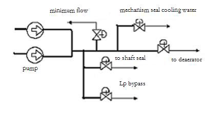

Tags: inverter, water supply
Frequency inverters have a great of prospect in application because the
inverter can save a large amount of electric energy when they are used
for fans.
Capacity of the Power Generation is 110MW. After reconstruction of 1# dedust fan, the power of fan increases 525kW. Variable frequency technology is an effective method to save energy. Variable frequency can realize soft start, reduce impact on equipment. In addition, inverter installation is very easy. It only series connects between breaker and motor. No need to change load and motor. It is necessary to use inverter to save energy for ID fan.
Inverter reform
Air flow is controlled by damper in 1# system. Big redundancy power and damper adjusting mode cause high power consumption.
Motor parameters ID fan parameters
model: Y560-8 Y4-73-11-27D
power: 1000kW flow:425700m3/h
voltage: 6kV pressure: 5064Pa
current: 118.6A media ℃: 90℃
frequency: 50HZ
speed: 744r/min
According to practical operation, inverter current can be 100A, 18.6A less than motor rated current 118.6A. After research market, we finally choose Gozuk inverter. The inverter current is 105A.
Bypass cabinet is installed to ensure system stability. When the frequency inverter is broken, motor can be switched to direct on line manually. Bypass circuit is composed of 3 breakers QS1, QS2 and QS3. QS2 and QS3 are interlocked. In variable frequency state, QS1 and QS2 close, QS3 opens. In direct on line state, QS3 closes, QS1 and QS2 open.
In order to protect inverter, we design link lock with QF. Once the inverter is broken, inverter switches off QF. In direct on line state, inverter cancels signal of QF trip-off to make motor run in direct on line.
Frequency inverter can also be equipped with upper PC. The PC is installed in control room. User can start/stop, set speed through PC. PC can show operation data and current state. User can also control inverter through operation platform.
Tags: inverter, Power Generation
